Power System Studies
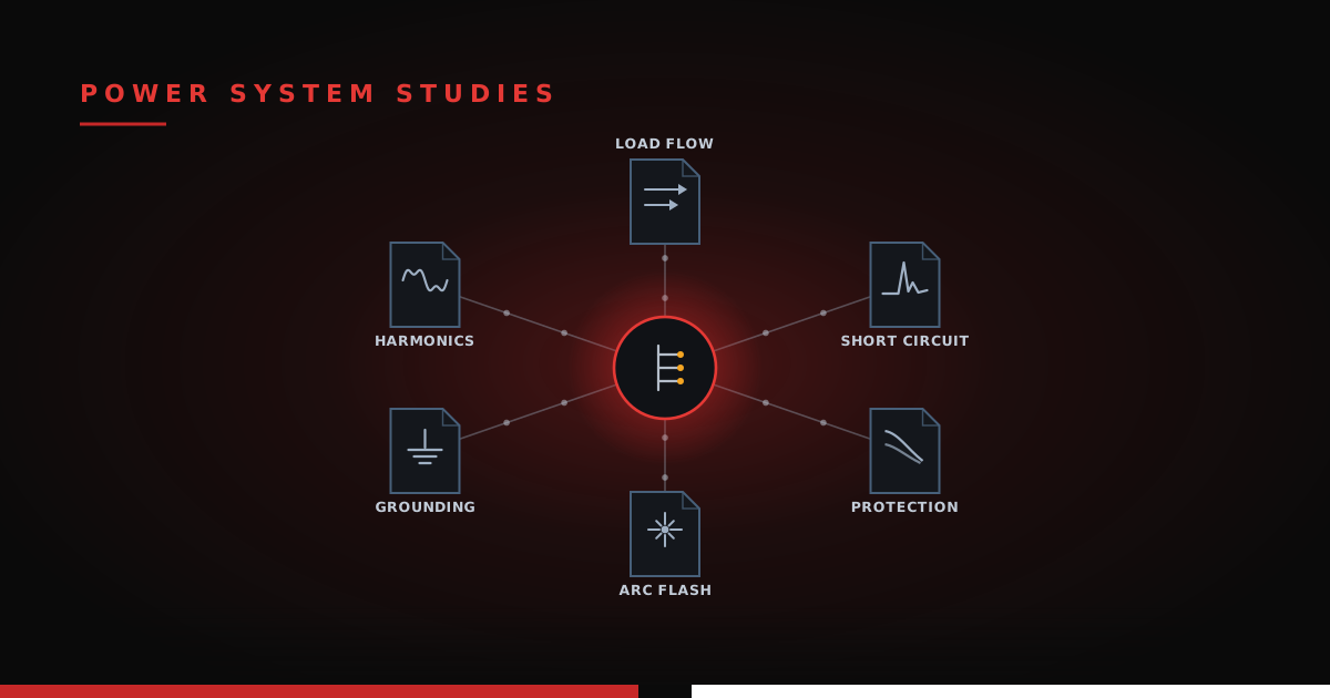
Why does every renewable energy project need its own set of engineers? With thousands of solar and storage plants already installed, why design a new one at all? Why not pull the last project's drawings off the shelf, dust them off, and build it again? It is a reasonable question, and at face value a logical one.
Two sites may share the same module, inverter, cable, and transformer, and even interconnect within the same utility's jurisdiction, yet still be wildly different designs. Subtle changes in ambient air temperature, soil characteristics, and the available fault current from the utility can each cause the old design to fail under the new conditions.
For example, a couple of degrees of change in the minimum or maximum air temperature can reduce a string by one module, which shrinks a four-string tracker row by four modules, which changes the structural assumptions, which changes the foundation design, and the effect keeps trickling across the whole site (we trace that exact chain in Calculating String Size).
Studies are where general engineering code meets site-specific calculation. Some exist to keep a site running efficiently, some to keep it safe, others to prove the energy production matches what the client was promised. The core of an engineered solar or storage project lives in its studies. Let's get into it.
WHO ACTUALLY REQUIRES THEM
Every study answers to a specific party holding a specific gate, and the project does not move until that gate opens.
The utility holds the biggest one: no plant connects to the grid without proving, on paper, that it will not drag the grid down with it. The authority having jurisdiction (AHJ), along with the NEC and NESC, governs safety on the plant side. IEEE standards set the methods and the pass/fail thresholds everyone else points to. Insurers and lenders want the stamped results in hand before they commit money, and once a plant crosses a certain size, NERC reliability standards stack on another layer. Behind every study in this post stands one of these gatekeepers, and none of them accepts "we did it this way last time" as an answer.
LOAD FLOW: THE STEADY-STATE PICTURE
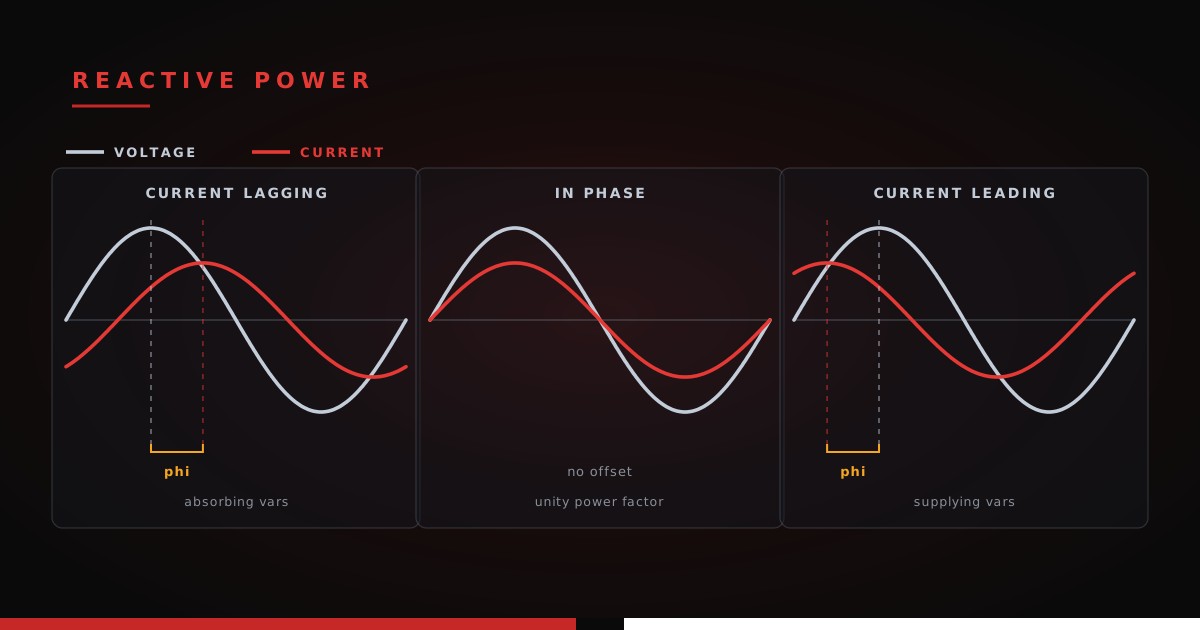
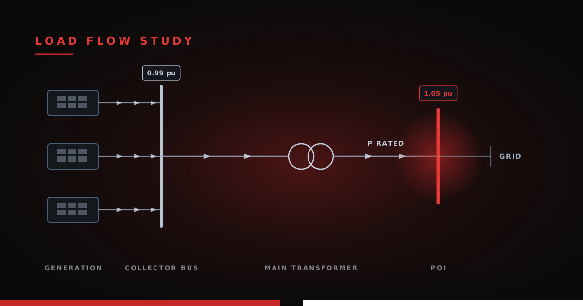
A load-flow study is the foundation, and almost everything else leans on it. It solves the plant at a moment in time: how much real and reactive power flows through each conductor and transformer, what the voltage is at every bus, and whether anything is overloaded or sitting outside its voltage band. It is how you confirm the plant can actually deliver its rated output to the point of interconnection (POI) while holding voltage where the grid code demands, which is exactly where the reactive-power and voltage requirements from the one-line diagram become real numbers.
The same study proves the plant can hold voltage and power factor at the POI across its entire output range, not just at full power. That envelope is the plant's capability curve, and meeting it is a grid-code obligation: IEEE 1547-2018 for distribution-connected resources, and IEEE 2800-2022 for larger inverter-based plants tying into the transmission system. Load flow is where you confirm the inverters, plus any reactive power hardware like capacitor banks and reactors, can deliver the required reactive power at the point that matters. Most modern inverters, solar and storage alike, can supply reactive power even at night when the plant is exporting no real power at all, so voltage support is no longer a daytime-only service.
For storage, load flow runs harder, because a battery has more operating states than a solar plant. You study full discharge and full charge, not just peak export, and you check the plant across its life as the battery is augmented and its internal impedances shift, each a different snapshot the study has to cover.
SHORT CIRCUIT: HOW BAD CAN A FAULT GET
Short circuit answers one blunt question: when a fault happens, how much current shows up, and where. That number sets the interrupting rating of every breaker, the withstand rating of every bus and cable, and the inputs to almost every study below it. Undersize for it and equipment fails explosively at the worst possible moment; the MV cable short-circuit withstand check is one narrow slice of this analysis.
Inverter-based plants add a wrinkle worth flagging early: solar inverters and battery PCS units do not dump the huge fault currents a spinning generator does. They are current-limited, typically to something like 1.1 to 1.2 times rated, and they clear fast. That low, controlled contribution is easy on equipment ratings but hard on protection, which is the next study's headache.
PROTECTION COORDINATION: TRIP THE RIGHT BREAKER
The protection coordination study incorporates all protection devices and equipment damage curves in a Time-Current Characteristic (TCC) curve for two main reasons. First, it is used to ensure that the protective devices trip before equipment is damaged. Most equipment can handle fault-level currents for a short amount of time, and this curve graphically demonstrates that an upstream device trips before it becomes an issue. The second reason is to ensure the closest protective device (or the preferred device) trips first. Take a transformer as an example: it has fuses built in to protect the transformer from becoming irreparably damaged. If these fuses blow, it requires a full inspection, draining of the insulating fluid, and potentially taking it out of service for a long while. Even though this is the closest protective device for the transformer, it is far more preferable to trip the upstream MV circuit breaker, which, once the fault has been cleared and the site repaired, can easily be put back in service with the push of a button.
ARC FLASH: THE LIFE-SAFETY HEADLINE
The arc flash study is one of the studies specifically done to protect human safety. It calculates the incident energy a worker would be exposed to if an arc flash occurred at a given piece of equipment. This study references IEEE 1584-2018 and NFPA 70E to run that calculation and generate the required safety labels. It is directly correlated to fault current and the clearing time, which is why faster protective settings are often the cheapest way to bring a dangerous number down.
Storage adds a second front - DC arc flash. The battery and the DC side of the PCS store enormous energy at high DC voltage. DC arc-flash analysis is less standardized than the AC side and easy to overlook as it requires involvement from the PCS and battery manufacturers to accurately model the protective devices within their equipment.
GROUNDING: SAFETY IN THE DIRT
When a fault pushes current into the earth, the soil around it rises in voltage. For anyone standing nearby, this becomes a safety issue as touching nearby equipment or simply taking a large step will trigger a discharge through the body.
A properly sized ground grid carries the fault current away without letting dangerous voltages build up under someone's feet or between their hand and a fence. The grounding study computes ground resistance, ground potential rise, and the step and touch voltages a person could be exposed to, then designs the grid of conductors and rods to keep them within safe limits.
The standard reference for substation, PV, and BESS grounding is IEEE 80-2013. PV gets an additional specific reference to accommodate the larger scale of land use, IEEE 2778-2020. Both rest entirely on the soil's electrical resistivity, which is why the geotechnical scope matters as much to the electrical engineer as the civil one; we cover that split in Thermal vs Electrical Resistivity.
HARMONICS: KEEPING THE POWER CLEAN
Inverters and PCS units build their AC waveform by switching very fast, and that switching injects harmonic distortion (higher frequencies than 60 Hz on the power lines) back onto the grid. Since AC equipment in the US is typically designed for 60 Hz, too much of these higher-frequency harmonics can overheat equipment, trip sensitive loads, and potentially violate the interconnection agreement. The harmonics study models the plant as a set of harmonic sources, predicts the distortion at the POI, and sizes filters if the numbers run hot.
The pass/fail limits come from IEEE 519-2022, which was updated specifically to handle grids full of inverter-based resources. Because a solar plant and a storage plant are both wall-to-wall power electronics, harmonics is rarely a study you get to wave off.
HOW THE STUDIES CONNECT
The studies are not a checklist of independent items; they are a chain. Load flow and short circuit are the two roots. Protection coordination grows out of short circuit; arc flash grows out of both short circuit and coordination; grounding leans on the fault currents too. Harmonics sits on top as the remaining compliance layer, alongside the reactive and voltage checks that live inside load flow, proving the plant plays nicely with the grid. Change one root and the branches move, which is why a late design change can quietly invalidate a stack of finished studies.
WHEN THEY HAPPEN
The studies land in waves across a project. Early on, the utility runs its own interconnection studies to see whether the grid can absorb the plant at all. Under FERC Order 2023, large plants now move through a first-ready, first-served cluster study that bundles power flow, short circuit, and stability analyses on a fixed timeline, rather than the old one-at-a-time queue. Then, as the design firms up, the engineer for the project produces the detailed on-site studies (short circuit, coordination, arc flash, grounding), and the final settings and labels get confirmed at commissioning before anyone throws the first breaker.
None of these studies is optional, and none stands alone: change the design and the whole chain shifts.