Calculating String Size
When designing a solar PV system, it’s imperative to land on the optimal configuration so the plant runs at high efficiency. One parameter that demands early attention is the DC voltage. Most projects in the US operate at 1500Vdc — though some are beginning to push to 2000Vdc — and this is the maximum input voltage rating on most utility-scale inverters. Why run the system so high? Because power is the product of voltage and current (P = IV), delivering a given amount of power at a higher voltage means proportionally lower current; and since conductor losses scale with the square of that current (I²R), trimming the current has an outsized effect on losses. It’s the same logic behind utility transmission and distribution lines running up in the kilovolt range (12.47kV, 69kV, 115kV, and beyond).
That approach works cleanly for bare overhead conductors, but solar PV cable is typically strung at chest height throughout the plant, so for operations and safety it has to be insulated. The trade-off with higher voltage is that the insulation must withstand the increased electrical pressure, which means thicker jackets or more expensive polymers. So we’re effectively capped at the 1500Vdc system, and to minimize energy loss we want to sit as close to that ceiling as possible without ever exceeding it.
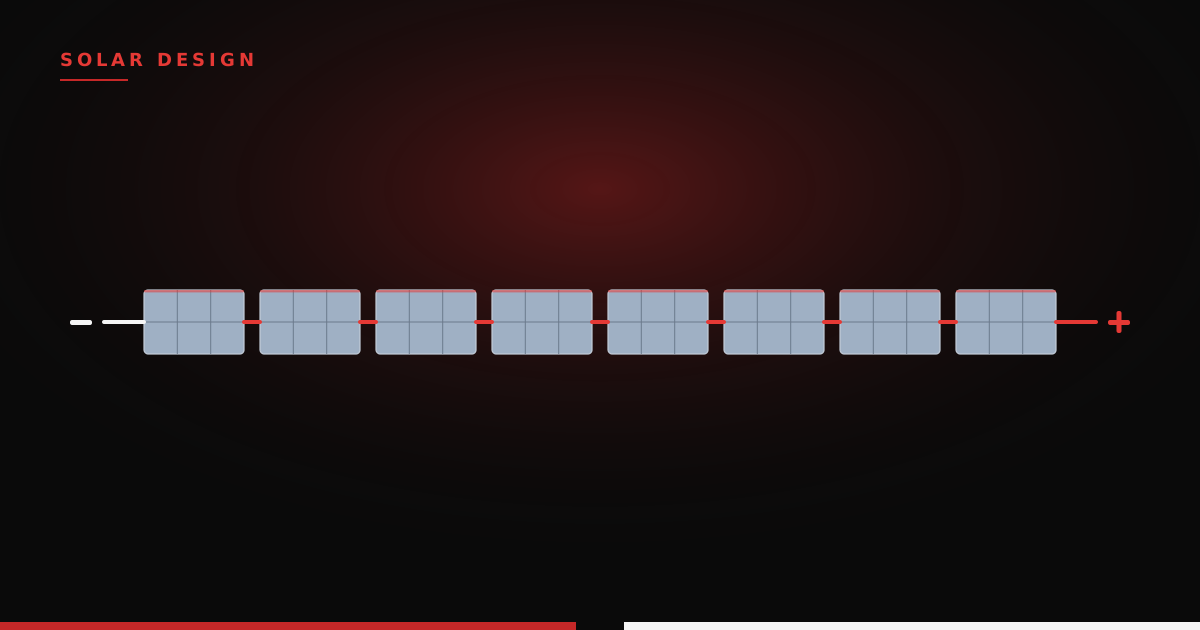
A single module typically has an open-circuit voltage somewhere in the 40–50V range, so multiple modules are wired in series to build up what we call a ‘string.’ Calculating the proper string size is fundamental to solar PV design, and it’s what we’ll work through in this post.
THE MAXIMUM STRING: COLD-WEATHER VOC
Let’s walk through a real-world example. Four values dictate the maximum string size for a given module, and each should appear on a commercial datasheet:
- The rated DC input voltage of the inverter [V]
- The open-circuit voltage (Voc) at standard test conditions (STC) [V]
- The temperature coefficient of Voc [%/°C]
- The minimum site temperature [°C]
As mentioned, most utility-scale inverters are rated for 1500Vdc — that’s our target, and we’re playing by Price Is Right rules: get as close as possible without going over. The open-circuit voltage (Voc) is a factory-measured value taken with no load attached to the module. Since current normally pulls voltage down, the no-load case gives us the maximally bounding scenario — in real-world terms, modules sitting in full daylight, pushing voltage onto an inverter that isn’t yet exporting power to the grid. The third value, the temperature coefficient, matters because a module’s output shifts with irradiance, temperature, and air mass. STC is defined as 1000 W/m², 25°C, and AM 1.5 — a solid reference point for high-level calculations, but one that can produce over-voltage events if it isn’t adjusted for site conditions. Module voltage decreases as ambient temperature rises, so the maximum voltage occurs at the minimum site temperature. For that figure, we recommend the latest ASHRAE “annual dry-bulb mean minimum temperature” from the nearest recording station.
Note: A project is unlikely to experience its minimum design temperature and 1000 W/m² of irradiance at the same moment. Designing for both at once simply builds in a healthy, conservative margin — the kind an engineer can comfortably stand behind.
Now for the math. Once you have the site’s annual minimum design temperature, find the difference between the STC temperature (25°C) and the ASHRAE value. Say our site has a minimum annual temperature of −20°C. The difference is −20°C − 25°C = −45°C, meaning the site’s minimum sits 45°C below STC.
Next, apply the Voc temperature coefficient. This value is almost always negative, which simply reflects the inverse relationship between temperature and voltage. For this example we’ll use −0.25%/°C. Multiply the temperature delta (−45°C) by the coefficient (−0.25%/°C) — watch your units — to get a correction factor of +11.25%.
Let our Voc at STC be 40V. Applying that scaling factor, the maximum Voc under site conditions is 40V + (40V × 11.25%) = 44.5V. The maximum number of series modules is then the floor of 1500Vdc ÷ 44.5V, or 33 modules.
Had we ignored the minimum site temperature and used the raw STC value, we’d have landed on 37 modules — enough to push the string past the 1500V limit on a cold morning (37 × 44.5V = 1646.5V).
WHERE THESE VALUES LIVE ON A DATASHEET
Before we go further, it’s worth pointing out where all these numbers actually come from. Every module value we need lives on the manufacturer’s datasheet, usually under a heading like “Electrical Characteristics” or “Electrical Data.” If you’ve never had to dig them out, they’re easy to lose among all the other specs. Below is a clean recreation of a typical utility-scale module datasheet, with the values that matter for string sizing highlighted.
| Electrical Characteristics (STC) | Symbol | Value |
|---|---|---|
| Maximum Power | Pmax | 450 W |
| Open-Circuit Voltage | Voc | 40.0 V |
| Short-Circuit Current | Isc | 14.50 A |
| Voltage at Maximum Power | Vmp | 33.0 V |
| Current at Maximum Power | Imp | 13.64 A |
| Module Efficiency | η | 20.7 % |
| Temperature Coefficients | Symbol | Value |
|---|---|---|
| Temp. Coefficient of Pmax | γ | −0.34 %/°C |
| Temp. Coefficient of Voc | β | −0.25 %/°C |
| Temp. Coefficient of Vmp | — | −0.35 %/°C |
| Temp. Coefficient of Isc | α | +0.045 %/°C |
| Nominal Operating Cell Temp. (NOCT) | — | 45 ± 2 °C |
For string sizing, only a handful of these do the heavy lifting: the open-circuit voltage (Voc), the voltage at maximum power (Vmp), and the temperature coefficient for each — the four highlighted rows above. Note that both voltages are quoted at STC (1000 W/m², 25°C cell temperature, AM 1.5), so every correction we make is relative to that 25°C baseline. The remaining two inputs — the inverter’s maximum input voltage and its minimum MPPT voltage — come from the inverter datasheet, while the site temperatures come from ASHRAE.
Note: Not every datasheet lists a separate temperature coefficient for Vmp. If yours doesn’t, the common workaround is to fall back on the Voc coefficient; just know that the true Vmp coefficient tends to be slightly more negative, so treat it as a reasonable approximation rather than an exact figure.
SIZING THE OTHER END: THE MINIMUM STRING
So far we’ve solved only half the problem. The cold-weather Voc calculation gives us the ceiling — the most modules we can safely put in series before risking an over-voltage event on a frigid morning. But every string has a floor too, and overlooking it is one of the easiest ways to quietly rob a plant of performance.
Here’s the flip side. Just as cold pushes voltage up, heat pulls it down. On the hottest days of the year, module voltage sags, and if a string is too short its operating voltage can fall below the inverter’s minimum MPPT voltage. When that happens, the inverter can no longer hold the string at its maximum power point — so you leave energy (and money) on the table, and in extreme cases the inverter drops offline entirely until conditions recover.
There’s an important wrinkle here that trips a lot of people up. For the cold case, we used ambient temperature directly, because Voc is a no-load measurement and a clear, cold morning before the inverter wakes up is about as close to ambient as a module ever gets. But the minimum-voltage case happens under full sun and full load, and a module baking in direct sunlight runs considerably hotter than the surrounding air. A good rule of thumb is that cell temperature sits roughly 25–30°C above ambient at full irradiance — which is exactly what the NOCT figure on the datasheet is hinting at. So for the minimum string calculation, we work in cell temperature, not ambient.
Let’s run the numbers. For the maximum design temperature, we pull the ASHRAE 2% annual cooling design dry-bulb value for our site — say it comes in at 40°C ambient. Adding a 25°C cell rise puts our design cell temperature at 65°C, which is 40°C above the 25°C STC baseline. Applying the Vmp temperature coefficient from the datasheet (−0.35%/°C):
40°C × (−0.35%/°C) = −14%
With Vmp at STC of 33V, the minimum Vmp under hot conditions is:
33V + (33V × −14%) = 28.4V
If the inverter’s minimum MPPT voltage is 875V, the minimum number of modules is the ceiling of 875V ÷ 28.4V, or 31 modules. Note that we round up here, not down; dropping below the MPPT floor is the very failure we’re trying to avoid, so we need at least this many.
PUTTING IT TOGETHER: THE MPPT WINDOW
Now the full picture comes into focus. A valid string isn’t bounded by the 1500V ceiling alone; it has to live inside the inverter’s entire MPPT voltage window, staying under the maximum on the coldest morning and above the minimum on the hottest afternoon. Stack our two results together, and the design envelope for this module-and-inverter pairing looks like this:
| Bound | Driven by | Condition | Result |
|---|---|---|---|
| Maximum modules | Cold Voc (over-voltage) | −20°C ambient | 33 |
| Minimum modules | Hot Vmp (MPPT floor) | 65°C cell | 31 |
| Valid string length | — | — | 31–33 modules |
In this example, the window is genuinely tight: anywhere from 31 to 33 modules per string will work, with no room for sloppiness on either end. It won’t always be this narrow — some module-and-inverter pairings give you a comfortable spread — but tight windows are common in real designs, and they’re exactly the situation where skipping the minimum calculation comes back to bite you. Design to the window, not just the ceiling.
COMMON MISTAKES TO AVOID
A few pitfalls come up again and again. These are the ones worth double-checking before you lock in a design:
- Using STC Voc without a temperature correction. This is the big one — it’s exactly the 37-module trap from earlier. STC numbers are a starting point, not a design condition.
- Using ambient instead of cell temperature on the minimum calculation. A module runs hotter than the surrounding air, and ignoring that cell rise makes the hot-day voltage sag look smaller than it really is, nudging you toward strings that are too short.
- Grabbing the wrong ASHRAE temperature. Reach for the mean minimum and the 2% design values, not the all-time record extremes. Designing to a once-in-fifty-years cold snap just leaves capacity on the table.
- Mixing up the Voc and Vmp coefficients. They’re different numbers, and leaning on the Pmax coefficient as a stand-in for both is a common shortcut that can quietly skew your margins. Use the right one for each bound.
- Ignoring the coefficient’s units. Datasheets quote temperature coefficients in either %/°C or mV/°C — confirm which one you’re holding before plugging it in, or your correction could be off by orders of magnitude.
- Forgetting DC voltage drop on long runs. On a large site with long homerun cables, real conductor voltage drop eats into your margins. It doesn’t change the string-length math directly, but it’s part of the same voltage budget and deserves a look.
A QUICK WORD ON 2000V SYSTEMS
You’ll recall from up top that some projects are beginning to move to 2000Vdc. The string sizing math doesn’t change — you’re still bounded by cold Voc on top and hot Vmp on the bottom — but the ceiling rises, letting you put more modules in series per string. Longer strings mean fewer strings overall, which translates into less wire, fewer combiners, and lower balance-of-system cost across a large plant. That economic pull is what’s nudging the industry toward 2000V, even as the insulation and equipment ecosystem catches up. If you’re designing at 2000V, just swap in your inverter’s actual voltage ratings and run the exact same process.
WRAPPING UP
Accurately sizing a string does two jobs at once: it protects the inverter from over-voltage and keeps the string operating where power loss is lowest. The key takeaway is that it’s a two-sided problem: the cold-weather ceiling and the hot-weather floor together define a narrow band of valid string lengths, and a solid design has to respect both. Get it right, and the string quietly does its job for the life of the plant. Get it wrong, and you’re either tripping over-voltage faults in winter or bleeding energy all summer.