MV Cable Short Circuit Withstand
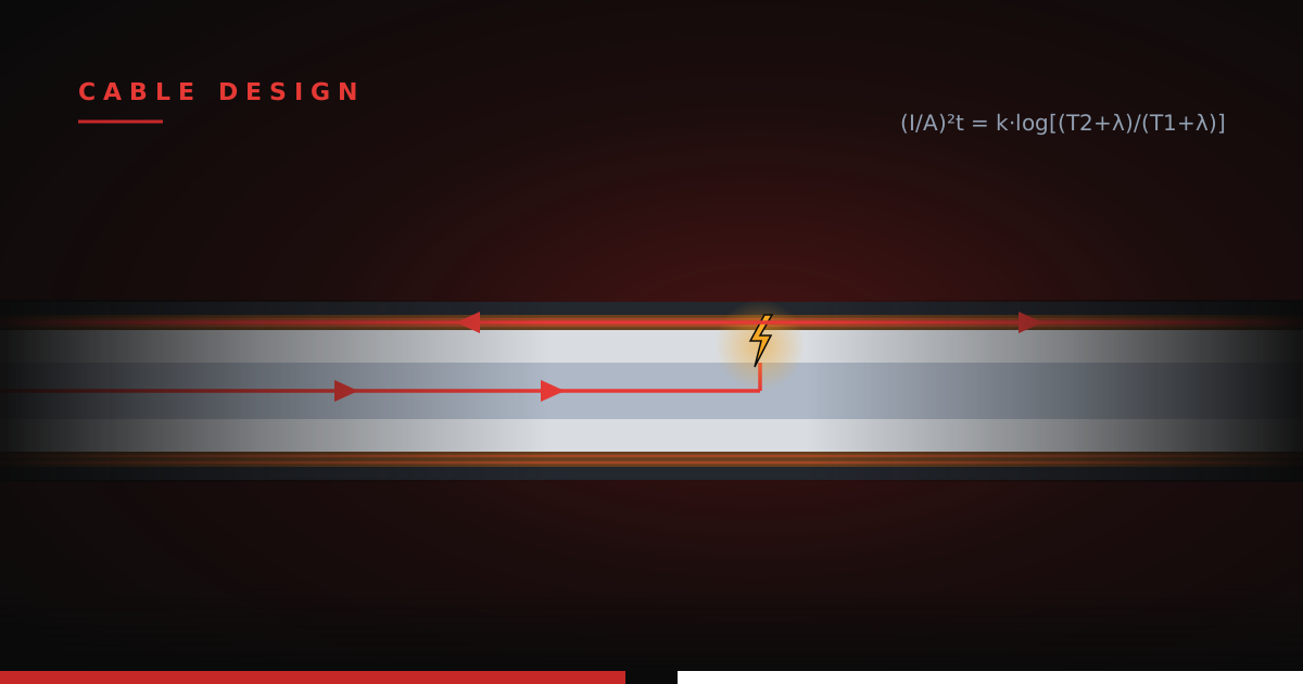
Ampacity gets all the attention in underground MV feeder design: duct bank geometry, soil thermal resistivity, load factor, conductor size. And it should get attention; it governs the everyday. But there's a second sizing check that too often gets treated as an afterthought, bolted on after the ampacity study is done: short-circuit withstand. Ampacity asks whether the cable can carry its load for thirty years. Withstand asks whether it can survive fifteen cycles (1 cycle = 1/60 second) of the worst day of its life. A cable that passes the first check and fails the second is a cable that works perfectly right up until a fault turns one repair into a mile of trench.
This post covers both withstand value checks for medium-voltage feeder cable — the phase conductor and the concentric neutral (CN) — the standards behind them, the design basis worth adopting, and the math itself. To assist in making these calculations, FluxState provides a companion tool that runs all of it: the MV Cable Short Circuit Withstand calculator.
WHY WITHSTAND IS NOT AN AFTERTHOUGHT
A short circuit subjects the cable to current one to two orders of magnitude above its ampacity rating, for a duration measured in cycles. No heat escapes in that time — the event is effectively adiabatic, meaning every joule of I²R heating stays in the metal. The question becomes brutally simple: does the conductor (phase or neutral) have enough cross-sectional area to absorb that energy without exceeding the temperature its insulation can survive?
Two separate checks fall out of this, because two separate parts of the cable carry fault current:
- The phase conductor carries the full fault current on its way to the fault. This is the through-fault case — a healthy cable feeding a fault downstream at the switchgear, transformer, or an adjacent section.
- The concentric neutral carries the return current home. On a jacketed, end-bonded system, the CN is the metallic return path wrapped around the conductor itself.
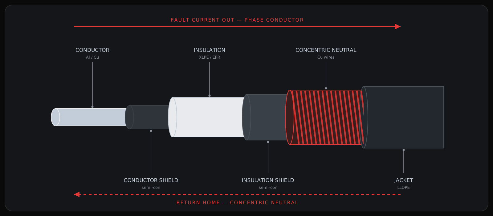
Fail the conductor check and the insulation at the conductor interface is damaged on a through-fault — on a cable that was otherwise healthy. Fail the CN check and the consequences are sneakier, which is where the design basis discussion below comes in.
A WORD ON ICEA
The standards governing these checks come from a group most engineers outside the cable world have never dealt with: the Insulated Cable Engineers Association. ICEA is not a typical standards body. It traces back to 1925 (originally the Insulated Power Cable Engineers Association), and it remains a small volunteer organization of practicing cable engineers — largely from the manufacturers themselves — rather than a broad-membership institution like IEEE or a trade association like NEMA. Its documents are frequently co-published through ANSI and NEMA, which is why the full citations read like alphabet soup.
Three of its documents matter here:
- ANSI/ICEA P-32-382 — short-circuit characteristics of insulated cable; the conductor withstand method.
- ANSI/ICEA P-45-482 — short-circuit performance of metallic shields and sheaths; the CN withstand method.
- ANSI/ICEA S-94-649 — the construction standard for concentric neutral cables rated 5 through 46 kV; where CN wire sizes and standard neutral fractions come from.
The obscurity is worth mentioning because it explains the afterthought problem: ampacity lives in the NEC and IEEE documents every power engineer touches, while withstand lives in slim ICEA publications that mostly cable specialists read. Unfortunately, physics does not care which book it is printed in.
THE DESIGN BASIS: 100% ON A SINGLE NEUTRAL
Grounding studies use a split factor — the fraction of ground-fault current returning through metallic paths versus earth, per IEEE 80. It's tempting to apply one here: three bonded CNs plus a trench ground share the return current, so size each CN for its share. For faults at equipment, where return current enters a ground bus and divides among parallel paths, that sharing is real.
Resist the temptation anyway, and here's the reasoning.
The withstand check protects against the failure that actually condemns cable: a fault on the cable itself. When insulation fails mid-cable run on a jacketed, end-bonded system, the return current enters the faulted cable's own CN at the fault point — and it has nowhere else to go. The jacket isolates the CN from earth along the run; the parallel neutrals and the trench ground can only pick up their share at the bonding points at the ends. Between the fault and the nearest bond, that single CN carries essentially everything.
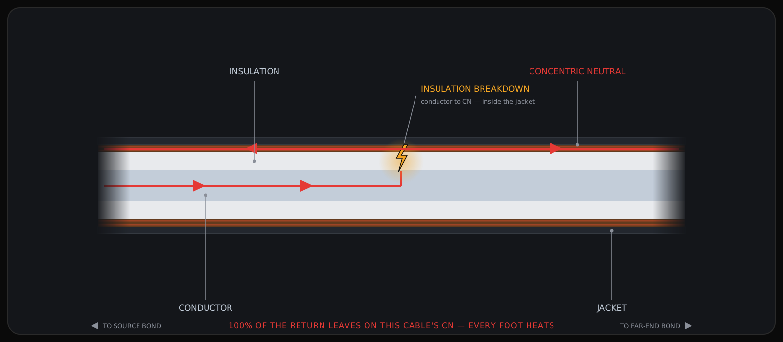
Now the part that changes the economics: adiabatic heating is per unit length. An undersized CN doesn't overheat just near the fault — every foot of neutral between the fault and the bond exceeds its temperature limit for the full clearing time. The faulted spot was always going to need a splice; that's a day of work. However, if the CN cooked along its whole length, the jacket and insulation are suspect for the entire run — and a one-splice repair becomes a section replacement. On a solar project, that's megawatts stranded while a new run is pulled.
Size the CN for 100% of the design fault current on a single neutral and that scenario disappears. The fault damages the fault location; the rest of the cable survives intact. The fix is simple: splice it and re-energize. The up front premium over a split-factor basis is modest, and what it buys is the difference between a maintenance event and an outage measured in weeks.
GROWTH FACTOR: DESIGNING FOR THE GRID YOU'LL HAVE, NOT THE GRID YOU'VE GOT
The fault current in a utility's interconnection study is a snapshot. It reflects the system as built today — today's transmission topology, today's generation, today's transformer impedances. None of that is static over a 35-year project life.
Every new interconnection in the electrical neighborhood (another solar plant, a BESS addition, a transmission reinforcement) stiffens the system and raises the available fault current at your bus. A cable sized to exactly today's fault duty is a cable that drifts toward undersized every time the utility's queue moves. And unlike a relay setting, conductor cross-section cannot be revisited later; it's buried.
The standard hedge is a growth factor applied to the studied fault current — utilities commonly specify 20%. Design fault = studied 1LG × 1.20. It's the same philosophy as designing structures for future load cases: the number is cheap insurance at design time and unobtainable afterward.
THE CALCULATIONS
Both checks use the adiabatic method: all fault energy heats the metal, no credit for heat escaping to surroundings. Conservative, simple, and appropriate for events measured in cycles.
Conductor withstand (ICEA P-32-382). The governing equation:
(I/A)² · t = k · log₁₀[(T₂ + λ) / (T₁ + λ)]
where 'I' is fault current (A), 'A' is conductor area (cmil), 't' is clearing time (seconds), 'T₁' is the starting temperature, 'T₂' is the limit, and 'k' and 'λ' are material constants (k = 0.0125 and λ = 228 for aluminum; k = 0.0297 and λ = 234 for copper).
The temperatures deserve a note. T₁ = 105 °C is just the MV-105 continuous rating (use 90 for MV-90). T₂ = 250 °C is not a property of the metal — aluminum melts at 660 °C and copper at 1083 °C. The limit is the insulation in contact with the conductor: 250 °C is what thermoset insulation (XLPE/EPR) tolerates transiently at the interface; thermoplastic drops that to 150 °C. The copper doesn't care; the organics do.
Shield/CN withstand (ICEA P-45-482). The neutral check runs through two intermediate constants:
K = 247×10⁻⁶ · SG · SH · (20 + λ) / P₀
M = √( K · log₁₀[(T₂ + λ) / (T₁ + λ)] )
I = M · A / √t
For copper CN wires: specific gravity 'SG' = 8.93, specific heat 'SH' = 0.092, resistivity 'P₀' = 1.72 μΩ·cm, 'λ' = 234. 'T₁' = 80 °C reflects the shield operating below the conductor; 'T₂' = 350 °C is the thermoset limit at the shield (200 °C for thermoplastic jackets). A is the total CN area — number of wires × area per wire, for one cable.
A worked example. Take a 1000 kcmil aluminum feeder with a 16 × 12 AWG copper CN — the standard 1/6 neutral for this size — a studied 1LG fault of 20,000 A, 20% growth factor, and 15-cycle clearing (0.25 s):
- Design fault = 20,000 × 1.20 = 24,000 A
- Conductor: I = 1,000,000 × √(0.0125 × log₁₀(478/333) / 0.25) = 88,596 A → PASS, +72.9% margin
- CN: K = 0.029967, M = 0.089864, A = 16 × 6,530 = 104,480 cmil → I = 0.089864 × 104,480 / 0.5 = 18,778 A → FAIL, −27.8% margin. Note it fails the raw 20,000 A too — the growth factor isn't what sank it.
- Minimum required CN for this duty: 24,000 × 0.5 / 0.089864 = 133,535 cmil. The fix is the next standard fraction up: a 1/3 neutral (32 × 12 AWG, 208,960 cmil) withstands 37,556 A and clears the duty with +36% margin.
Note the shape of the result: the conductor sails through with margin to spare — on large feeders it nearly always does — while the 1/6 neutral fails outright. A catalog cable that passes every ampacity check on the books would still cook its neutral end-to-end on the first internal fault; nothing about the datasheet warns you. That's the pattern that makes the CN check the one that actually drives decisions, and the one most worth automating. The calculator runs both checks, flags pass/fail for each, and shows every intermediate value so the work is reviewable.
Two levers move the answer more than anything else. The first is clearing time: it enters the equation as √t, so faster ground-fault relaying cuts the required area substantially — protection settings sometimes buy withstand cheaper than copper does. The second is the CN fraction: the standard offerings (full neutral through 4/0, 1/3 for 250–750 kcmil, 1/6 at 1000 kcmil and up) set what's actually orderable, so the real decision is usually which standard neutral clears the duty.
KEY TAKEAWAYS
- Withstand is a first-class sizing check, not a footnote to ampacity. Ampacity covers the everyday; withstand covers the fifteen cycles that determine whether a fault is a splice or a replacement.
- Two checks, two ICEA standards. Conductor per P-32-382, concentric neutral per P-45-482 — both adiabatic, both driven by insulation temperature limits, not metal melting points.
- Size the CN for 100% of the design fault on a single neutral. Split factors describe real current sharing for equipment faults, but a cable-internal fault puts everything on the faulted cable's own CN — and adiabatic heating condemns the whole run, not just the fault point.
- Apply a growth factor — 20% is the common utility number. Fault current only goes up as the neighborhood builds out, and buried conductor can't be resized later.
- Clearing time is the cheapest lever. Required area scales with √t; check the relaying before upsizing the neutral.