One Line Diagram Explained
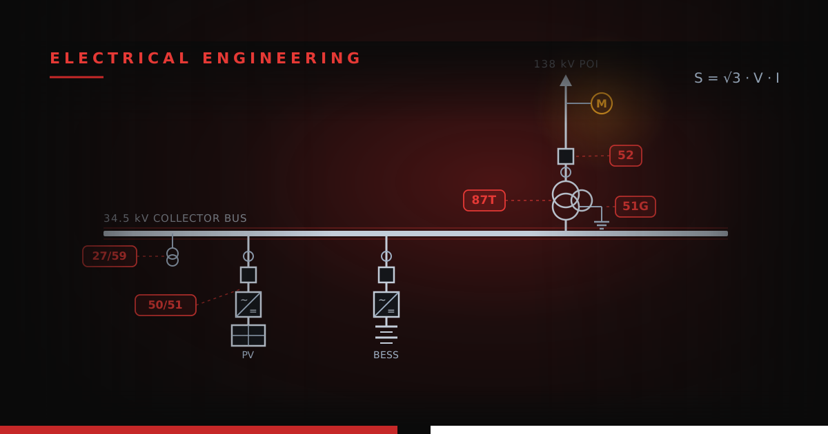
Every solar and storage project has one drawing everybody references and fewer people can actually read end to end: the one-line (sometimes also called a single line diagram). It's the map of the entire electrical plant — every breaker, transformer, relay, and cable compressed into a single page of symbols and cryptic numbers. Developers initial it, PMs schedule around it, and engineers argue over it. The numbers scattered across it in little boxes (52, 87T, 51G) all come from one standard, and once they click, a one-line stops being hieroglyphics and starts being a story.
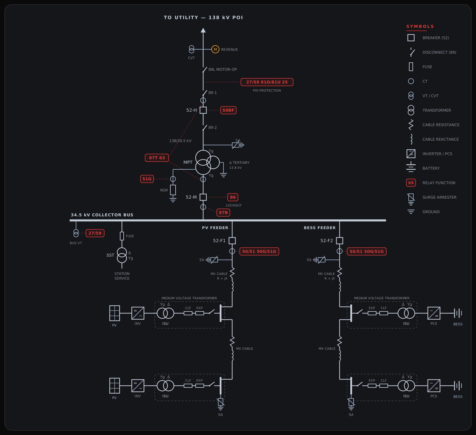
This post walks a representative hybrid-site one-line: a PV feeder and a BESS feeder on a shared 34.5 kV collector bus, stepping up through a substation to a 138 kV point of interconnection. Everything on it appears on real project drawings - albeit with many more generation devices.
HOW TO READ THE MAP
Three conventions unlock the whole drawing. First, the name one-line means only one of the three phases is shown. For a balanced system — a safe assumption for utility-scale projects — each phase is identical, and drawing all three conductors would triple the ink without adding any information. Second, the dashed boxes are equipment boundaries. Often several devices sit inside a single enclosure the manufacturer ships as one unit; the boundary makes that inclusion explicit for procurement and ownership. Third, the numbers in the red chips are IEEE C37.2 device functions — a shared shorthand where 52 always means a breaker and 87 always means differential protection, on every drawing from every utility.
Orientation runs top to bottom: utility at the top, generation at the bottom, power flowing up the page (and reversing when the BESS charges).
THE PLANT SIDE
Start at the bottom, where the energy comes from. Each feeder ends in the same repeating unit: a source, a converter, and a pad-mount transformer.
On the PV side, the array feeds a central inverter — the DC-to-AC frontier. On the BESS side, the same box is called a PCS (power conversion system) because it works both directions: discharging the battery to the grid and charging it back. Electrically they're cousins; contractually and functionally they're different animals. (Sometimes the PV inverter is coupled with a transformer and called a PCS too.)
The inverter's output is low voltage — 600 to 800 V — which would be absurd to haul across a mile of site. The ISU (inverter step-up) transformer, sometimes called a medium-voltage transformer (MVT), lifts it to 34.5 kV. Note the winding symbols: delta on the MV side, grounded-wye on the LV side, which keeps each block's ground behavior contained.
The ISU lives inside a steel-dashed boundary — labeled medium-voltage transformer on the drawing — along with a load-break switch, two fuses, and a short MV bus; together they make up the loop-fed padmount. The MV bus has an incoming cable landing at the top and an outgoing cable leaving the bottom: the feeder threads through every pad in the row, which is what "loop-fed" means. The two fuses in series serve complementary roles. An expulsion fuse (EXP) clears everyday overloads cheaply, while a current-limiting fuse (CLF) exists for the catastrophic fault, chopping the current before its first peak. One is replaced after a bad day; the other prevents the bad day from getting worse.
Two more details reward a close look. The zigzag-and-coil on each feeder is the MV cable itself, drawn as the series impedance it actually is — R + jX. That impedance is why long collection runs get checked for voltage drop; the NEC Voltage Drop calculator runs exactly that math. And the surge arresters (SA) sit at the cable ends — one at the feeder's head, one hanging off the final pad's bus — because cable ends are where traveling waves from lightning and switching reflect and double.
THE SUBSTATION
Everything funnels into the 34.5 kV collector bus — the horizontal backbone. Hanging off it: the feeder breakers (52-F1, 52-F2), a fused station service transformer (SST) that keeps the lights and relays alive, a bus VT for voltage sensing, and the main power transformer.
Breakers and switches divide the world between them. A 52 is a breaker: it interrupts fault current — thousands of amps, mid-arc. An 89 is a disconnect: it establishes a visible open point for safety but interrupts nothing. The 89-1/89-2 pair around breaker 52-H exists so crews can isolate the breaker itself for maintenance, and the 89L at the gen-tie is motor-operated so the plant can be sectionalized remotely.
The MPT deserves its three circles. It's a three-winding transformer: 138 kV grounded-wye primary, 34.5 kV grounded-wye secondary, and a 13.8 kV delta tertiary, one corner carried out to a ground symbol. The tertiary is the unsung workhorse — it gives zero-sequence current a place to circulate, which stabilizes the grounding of both wye windings and traps triplen harmonics. On the neutral, the NGR (neutral grounding resistor) sets the plant's ground-fault personality: it caps how much current a single-line-to-ground fault can drive, and every downstream ground relay — and every concentric neutral — is sized around that cap.
Instrument transformers are the sensory organs. CTs (the small circles on the conductors) scale thousands of amps down to relay-sized signals; VTs and CVTs do the same for voltage. The amber M at the top is the revenue meter — the only device on the drawing that directly produces an invoice.
PROTECTION, CONTROLS, AND METERING
Every red chip is a relay function, and each one answers a single question.
The feeder relays (50/51, 50G/51G) are the workhorses: instantaneous and time-overcurrent for phase faults, plus their ground-fault twins. The 51G on the MPT neutral CT is the backstop for the whole collection system — any ground current that flows through the NGR flows through it.
The 87s are differential relays: current entering a zone must equal current leaving it, and any imbalance means a fault inside. Each differential's zone is bounded by its CTs — 87T watches the MPT from the high-side CTs to the low-side CTs; 87B does the same for the collector bus. Differentials are fast and surgical, tripping only for faults inside their zone, with no intentional time delay. The 63 riding with 87T is the sudden-pressure relay, the transformer's internal fault detector.
At the POI, the utility's requirements live: 27/59 (under/overvoltage) and 81O/81U (over/underfrequency) define the envelope the plant must stay inside, and 25 (synchronism check) verifies both sides match before a breaker recloses the plant onto the grid.
Then the failure managers. 50BF is breaker failure: if 52-H is told to trip and current keeps flowing, 50BF clears everything around it. The 86 is the lockout relay — after a serious trip (87T, 87B, 50BF) it latches everything open until a human resets it, on purpose. Together these devices set the plant's clearing times — and clearing time is the √t in every cable withstand equation. Faster protection literally shrinks the copper a design needs; that trade is quantified in the MV Cable Short Circuit Withstand calculator.
One device is conspicuously absent, and the absence is the lesson: there is no 79 (reclosing) on the collection feeders. Utility distribution recloses because most overhead faults are temporary — a branch, a squirrel, wind. Underground cable faults are never temporary, and inverters aren't synchronous machines that can ride through a reclose attempt. A solar feeder that trips stays tripped until someone finds out why.
THE DEVICE KEY
| Device | Name | Where it lives on this one-line |
|---|---|---|
| 25 | Synchronism check | POI package — verifies both sides match before closing |
| 27 / 59 | Under / overvoltage | Collector bus VT and POI package |
| 50 / 51 | Instantaneous / time overcurrent | Feeder relays at 52-F1, 52-F2 |
| 50G / 51G | Ground overcurrent | Feeder relays; 51G also on the MPT neutral (NGR) |
| 50BF | Breaker failure | At 52-H — clears the next zone up if the breaker sticks |
| 52 | AC circuit breaker | 52-H, 52-M, 52-F1, 52-F2 |
| 63 | Sudden pressure | Bundled in the 87T chip; transformer-mounted |
| 81O / 81U | Over / underfrequency | POI package |
| 86 | Lockout relay | At 52-M — latches after major trips, manual reset |
| 87B | Bus differential | By the collector bus; reads the transformer-incomer CT |
| 87T | Transformer differential | Left of the MPT; leads to its high- and low-side CTs |
| 89 | Disconnect switch | 89-1/89-2 around 52-H; 89L motor-operated at the gen-tie |
| M | Revenue meter | At the POI, on the CVT |
KEY TAKEAWAYS
- A one-line is three languages at once — equipment (the symbols), boundaries (the dashed boxes), and protection (the C37.2 numbers). Read all three and the drawing narrates itself.
- The plant side repeats one unit: source → inverter/PCS → ISU inside a loop-fed padmount, with two-stage fusing and arresters at the cable ends.
- The MPT's delta tertiary and NGR set the plant's ground-fault behavior — every ground relay and every concentric neutral downstream is sized around that choice.
- Differentials protect zones; overcurrent protects everything else. Trace each relay's dashed CT leads to see exactly what it watches.
- Clearing time is a design variable, not trivia — 50BF and 86 determine how long faults last, and √t flows straight into cable withstand sizing.
- No 79 on purpose: underground faults are permanent and inverters don't ride through recloses. A tripped solar feeder stays down until diagnosed.