Thermal vs Electrical Resistivity
Soil testing is vital for project civil and structural design, but it also plays a large role in effective electrical design. "Soil resistivity", while the term gets used frequently, is a bit of a misnomer because it represents two similar but distinctly different parameters: thermal resistivity and electrical resistivity. Confuse them at your peril; they measure different things, with different instruments, and they feed different parts of the final design. It's a mix-up that trips up project managers, developers, and engineers alike, precisely because both parameters share a name and both correlate directly with soil moisture content.
Let's break down the differences, and why both matter to a complete design.
ONE REPORT, TWO PROPERTIES
A single geotechnical campaign typically gathers both electrical and thermal resistivity values - but "gathering both" only happens if both are actually specified, and they answer genuinely different questions:
- Thermal resistivity — How well does this soil shed heat? It sets how much current an underground cable can carry before it overheats.
- Electrical resistivity — How well does this soil conduct current? It sets how safely a fault can be pushed into the earth through a ground grid.
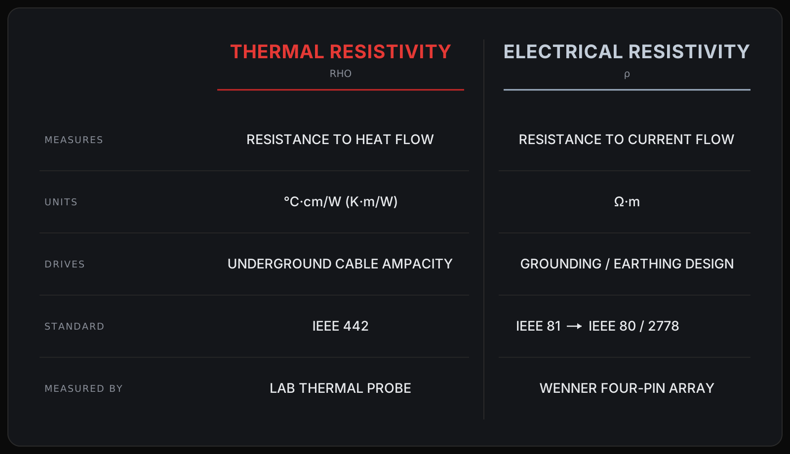
Same word, "resistivity"; different physics, different units, different instruments, different analyses. The rest of this post is really just those two columns, side by side.
THERMAL RESISTIVITY
Thermal resistivity, often written RHO, in units of °C·cm/W (or K·m/W in SI), measures how strongly the soil resists the flow of heat. A buried cable is a heater; the surrounding soil is what carries that heat away. High thermal resistivity means the soil is a good thermal insulator, heat piles up around the conductor, and the cable has to be de-rated or upsized to keep from cooking. It's the foundation of every underground ampacity calculation - the same RHO that the load-factor analysis is built on.
Two things move it most:
- Moisture - Wet soil sheds heat far better than dry soil, because water bridges the air gaps between grains. Dry soil is a thermal blanket.
- Density - Compacted soil has more grain-to-grain contact, so heat crosses it more easily. Loose or poorly placed backfill traps heat.
There's a failure mode worth knowing, because it's where thermal resistivity turns dangerous: dry-out. A hot cable can drive moisture away from itself, and as the soil around it dries, its thermal resistivity climbs — which makes the cable hotter, which dries the soil further. Left unchecked, that's a slow thermal runaway. It's why the dry thermal resistivity and the critical moisture content matter, not just the value on a good day.
Thermal resistivity is measured per IEEE 442: a slender heated probe is inserted into a compacted soil sample in a laboratory environment, and the rate at which it warms up reveals how quickly the soil carries heat away. Good practice tests across a range of moisture contents to map the soil's dry-out curve - resistivity versus moisture - so the design rests on a credible worst case, not the day the crew happened to visit. Selecting the correct moisture and compaction values is an important step in a full thermal ampacity study.
ELECTRICAL RESISTIVITY
Electrical resistivity (commonly abbreviated with the symbol ρ), in units of ohm-meters (Ω·m), measures how strongly the soil resists the flow of electrical current. It governs grounding: how effectively a ground grid can push fault current into the earth, and how much dangerous voltage shows up at the surface while it does.
When a fault dumps current into a ground grid, three things ride on the soil's electrical resistivity:
- Ground resistance — how low the grid's resistance to remote earth can get. High-resistivity soil makes a low-resistance ground hard and expensive to achieve.
- Ground potential rise (GPR) — how far the whole grid's voltage floats above true earth during a fault.
- Step and touch potentials — the voltage a person could be exposed to between their feet, or between hand and feet, standing near energized equipment. These are the life-safety numbers.
Electrical resistivity is the primary input to IEEE 80 (AC substation grounding) and, for PV plants specifically, IEEE 2778. Get it wrong and the ground grid is either unsafe or wildly over-built.
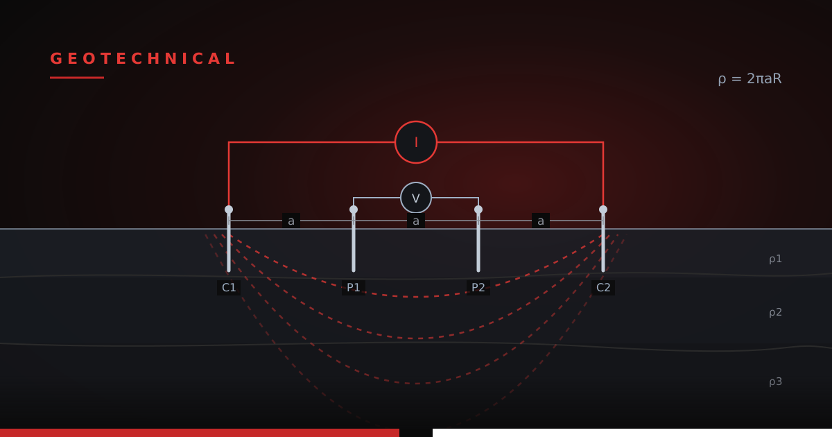
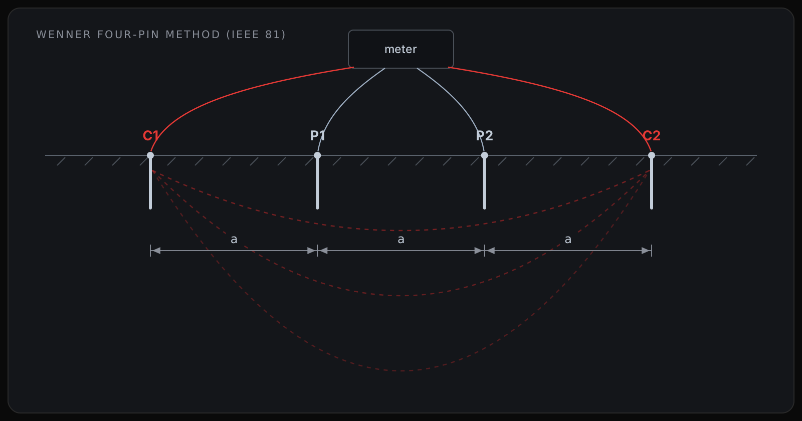
It's measured per IEEE 81, and the workhorse is the Wenner four-pin method: four electrodes are driven into the ground in a straight line at equal spacing. Current is injected through the outer two, voltage is read across the inner two, and the apparent resistivity follows from a simple relationship — ρ = 2πaR, where 'a' is the electrode spacing and 'R' is the measured resistance. Widening the spacing pushes the current deeper, so sweeping a from small to large builds a picture of resistivity versus depth; which matters, because soil is usually layered and a large grid "sees" the deeper layers. A full test report typically includes multiple measurements at spacing intervals from one to a couple hundred feet. These values are used to fit a soil profile curve in grounding software (typically WinIGS, ETAP, or CDEGS).
WHAT TO ACTUALLY SPEC
For whoever writes the geotech scope, the fix is simple and cheap: name both, explicitly.
- Call out thermal resistivity per IEEE 442, with a moisture or dry-out curve, for the cable ampacity study.
- Call out electrical resistivity per IEEE 81 (Wenner soundings across a range of spacings) for the grounding work.
Ensure the scope is clear, and don't settle for "soil resistivity test" - chances are you'll get one or the other. Confirm the quantity and location of testing areas are sufficient to build a representative model of the project. And if any imported soil fill is needed, be proactive about getting these values too, for a robust design.
KEY TAKEAWAYS
- There are two soil resistivities, not one. Thermal resistivity governs cable ampacity; electrical resistivity governs grounding. They are different properties that happen to share a name.
- Thermal resistivity (RHO, °C·cm/W) measures heat shedding — tested per IEEE 442 with a needle probe, driven by moisture and density, with dry-out as the failure mode.
- Electrical resistivity (ρ, Ω·m) measures current conduction — tested per IEEE 81 with the Wenner four-pin method, feeding IEEE 80 and 2778 for ground resistance, GPR, and step-and-touch.
- Both drop with moisture, which is why they get confused — but they use different units, different instruments, and different analyses, and one can't substitute for the other.
- Spec both, by name. Put IEEE 442 thermal and IEEE 81 electrical resistivity on the geotech scope explicitly; never let a single "soil resistivity" line stand as a complete answer.