Battery Storage, Demystified
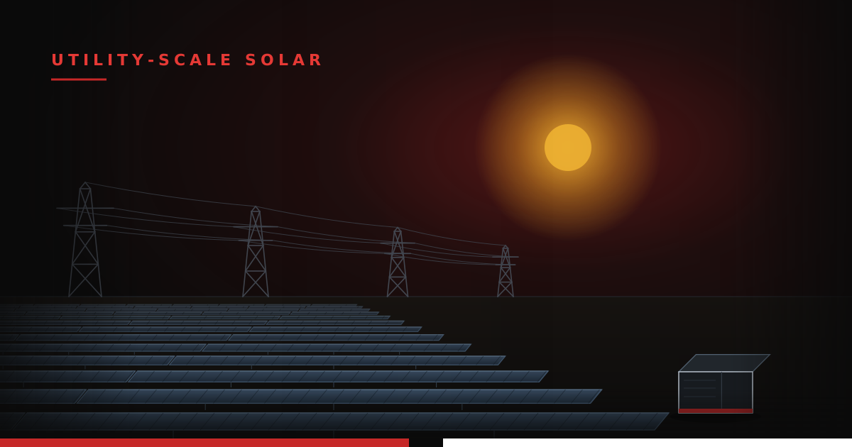
Utility-scale battery storage has crossed over from novelty to default. Some of it rides along with solar - a row of what look like shipping containers parked next to the array - and a fast-growing share is built stand-alone: a storage plant with no generation of its own, sited wherever the grid needs it most.
The reason is the same in both cases: timing. Solar makes its cheapest, most abundant energy in the middle of the day, exactly when demand is lowest. The grid, meanwhile, needs the most power in the early evening, after the sun is gone. A battery energy storage system (BESS) closes that gap; it soaks up cheap, surplus midday energy and dispatches it hours later, when power is scarce and expensive. Along the way it also steadies frequency, holds voltage, and stands by as backup, but the headline job is moving energy across the hours of the day.
This post is a plain-language tour of one: what's inside the box, how it's spec'd, how it ties into the plant, and why almost every conversation about a BESS eventually circles back to fire.
FROM CELL TO CONTAINER
A grid battery is built up in layers, and each layer has a name worth knowing because they all show up on drawings and datasheets.
It starts with the cell - the actual electrochemical unit, the thing that stores the energy. Utility storage has overwhelmingly settled on one chemistry: LFP, lithium iron phosphate (LiFePO₄). Roughly 90% of batteries deployed worldwide in 2025 were LFP, and closer to 95% of new utility-scale awards. It won for three reasons: it's cheaper than the nickel-based NMC chemistry used in most EVs, it tolerates far more charge/discharge cycles, and, critically, it's much harder to set on fire. LFP gives up some energy density for that safety and longevity, which is a trade a stationary project is happy to make when it isn't trying to fit into a car.
A modern LFP cell is a prismatic block about the size of a thick paperback, 3.2 volts, and the industry standard has marched from 280 amp-hours to 314 Ah in the last couple of years, with even larger formats arriving.
To put that in perspective: at 3.2 V and 314 Ah, a single cell holds almost exactly a kilowatt-hour of energy - think 250 AA batteries fused into one block, or a bit more than a car battery - and a single 20-foot enclosure packs close to 5,000 of them.
Stack cells together and you get a module. Stack modules in series and you get a rack - a floor-to-ceiling cabinet that pushes the DC voltage up to roughly 1,100–1,500 V, because higher voltage means lower current means thinner, cheaper copper.
Line racks up inside a weatherproof steel box and you get the enclosure - the "container" you see on site. The 314 Ah cell is the reason a standard 20-foot enclosure now holds about 5 MWh, up from ~3 MWh just a generation of cells ago, with around a dozen racks inside. That enclosure isn't just a shelf for batteries. It's a climate-controlled room: most new systems are liquid-cooled, circulating coolant to hold every cell within a few degrees of its neighbors, because a battery that runs hot ages fast and fails ugly.
Two more things live in that box and rarely get explained. The BMS (battery management system) is the nervous system - a hierarchy of controllers watching the voltage, temperature, and current of every module, balancing cells so they age evenly, estimating state-of-charge and state-of-health, and tripping the system offline the instant something drifts out of bounds. And the DC termination cabinet (sometimes a combiner or "DC panel") is where all the rack outputs land - the fuses, contactors, and disconnects that gather the racks' DC and hand it off to the power electronics. It's the battery's equivalent of the padmount and fuses on the solar side.
HOW TO READ A SPEC SHEET
A BESS spec sheet is dense - chemistry, voltages, currents, efficiencies, temperatures, protection, and a wall of standards, all of which matter. But two numbers trip people up more than any others, so start there and work outward.
Power is megawatts (MW) - how fast the battery can push or pull energy at any instant. It's set by the power electronics and the wiring. Energy is megawatt-hours (MWh) - how much it can store in total. It's set by the cells. A "100 MW / 400 MWh" system can deliver 100 MW for four hours before it's empty. That ratio - energy divided by power - is the duration, and four hours is the current sweet spot for most markets.
Flip the ratio over and you get the C-rate, the piece of shorthand you'll see everywhere. C-rate is power relative to energy: 1C means the battery discharges its full energy in one hour, 0.5C in two hours, 0.25C in four. Think of it as how fast you're draining the tank. Utility projects usually run gentle C-rates (0.25C–0.5C), and that's deliberate; pulling energy slowly keeps the cells cool, efficient, and long-lived. A datasheet that quotes capacity "at 0.5C" is telling you it was measured at a two-hour rate; the same cell delivers a little less if you yank on it harder.
Now work down to the AC section and find the maximum output current; that one number sizes the wire and the protection. Datasheets give it to you one of two ways. Some list it directly as a termination current: one integrated unit spells out its low-voltage output as 352 A × 3-phase × 6 - 352 amps per phase at each of six output terminations. Others give it indirectly as an apparent power at a stated voltage - 2,400 kVA at 480 V AC - which you turn into current with I = kVA × 1000 ÷ (√3 × V), or about 2,887 A.
Either way, that maximum continuous current sets the OCPD - the overcurrent protective device, the feeder breaker or fuse - and the conductors that carry it. Because a battery discharges for hours on end, the NEC treats it as a continuous load, so the OCPD and conductors are sized to at least 125% of that current. Get it wrong and the feeder either nuisance-trips or runs hot; it's the same current the downstream cable has to survive on a fault, which is where the NEC Voltage Drop calculator and the MV Cable Short Circuit Withstand calculator come in.
A few more numbers earn a close read:
- Round-trip efficiency (RTE) - how much energy you get back out versus what you put in, measured AC-to-AC. Good utility systems land around 85–94%. The missing few percent is lost in the cells, the conversion electronics, and, easy to forget, running the cooling and controls. Watch the fine print: RTE is usually quoted at 25°C on Day 1, so it's a best case.
- Cycle life - how many full charge/discharge cycles the cells survive before capacity fades to a defined floor (often 70–80%). Modern LFP cells are rated for 8,000+ cycles, which is what makes daily cycling for 15–20 years pencil out.
- Degradation and augmentation - this is the one that surprises people. A battery loses capacity every year from both use and age, so a plant contracted to deliver, say, 400 MWh for 20 years won't hold 400 MWh on its own. The fix is augmentation: adding capacity over time - extra racks or whole containers - to top the system back up to its guaranteed number. The manufacturer publishes a degradation curve - almost always a separate document or warranty exhibit - projecting how capacity fades year by year, and that curve is exactly what you use to time the augmentations. It's often the difference between two bids that look identical on day one.
TYING IT TO THE PLANT: THE PCS
The batteries speak DC. The grid speaks AC. The translator is the PCS - the power conversion system, a bidirectional inverter that turns the battery's DC into grid AC when discharging and back into DC when charging. It's the same family of device as a solar inverter, but it runs both directions. (On the plant one-line, the PCS is the box that looks like a solar inverter but earns the name PCS precisely because it's a two-way street.)
Where the PCS physically lives varies by vendor, and it changes what actually leaves the box. Many systems integrate the PCS inside the enclosure, so the unit puts out AC directly and needs no DC connections made in the field (some vendors advertise exactly that: "no DC connections required on site"). In an integrated unit like this, the battery, DC termination, and PCS ship as one AC-output block. Other designs keep the enclosure DC-only and wire it to a separate, external PCS nearby, so the box outputs DC and the conversion happens a few feet away. Knowing which you have tells you whether the fence line sees AC or DC, and where the DC termination and its protection actually sit.
In a hybrid plant there's a second, related choice: whether the storage is AC-coupled or DC-coupled to the solar. AC-coupled keeps the two independent; each has its own inverter and ties into the medium-voltage collection bus on its own feeder. DC-coupled wires the battery onto the same DC bus as the array through a DC-DC converter, so the two share a single inverter, which lets the battery capture solar energy that would otherwise be clipped when the array outproduces its inverter.
Either way, the AC side of the BESS lands on the collection system like any other feeder, which means the same cable questions apply - voltage drop across the run, short-circuit withstand on the conductors - and the same tools solve them.
SAFETY IS THE WHOLE GAME
Here's the thing about storing a few thousand kilowatt-hours of chemical energy in a steel box: the entire discipline of BESS design is organized around what happens if it goes wrong.
The failure everyone plans for is thermal runaway. A single cell overheats - from a defect, abuse, or overcharge - and starts an exothermic reaction that heats its neighbors, which do the same, cascading down the rack. LFP raised the bar here (it doesn't shed oxygen the way NMC can, so it's far more reluctant to ignite), but a failing LFP cell still vents hot, flammable gas. The job of the design is to detect trouble early, stop the cascade, keep the vented gas from exploding, and make sure that if something does burn, it doesn't spread to the next container or hurt anyone.
That job is governed by a stack of standards that reference each other, and it's worth knowing which does what:
- UL 9540 is the product listing; it certifies that the system (batteries, PCS, controls, enclosure) is built and wired to a recognized safety standard.
- UL 9540A is not a pass/fail rating; it's a test method. Engineers deliberately drive a cell into thermal runaway and measure what comes out - which gases, how much, how fast, and whether fire propagates from cell to module to unit. That data is the evidence base for everything else.
- NFPA 855, the installation standard (2023 edition, referenced by the International Fire Code), is where that test data turns into site rules: how far apart units must sit, maximum stored energy per group, fire detection and suppression, and explosion control. Because the vented gas can accumulate, systems pair gas detection tuned to the lower flammable limit with deflagration venting - panels sized per NFPA 68 to blow out and relieve pressure before an enclosure can - and, increasingly, active ventilation per NFPA 69. On a real datasheet you'll see exactly this: an NFPA 68 vent panel, smoke and heat detectors, and a small fire alarm control panel as standard, with sprinklers, gas detection, and NFPA 69 ventilation as options.
If it feels like the batteries are the easy part and the fire engineering is the hard part, that's not far off; it's the single biggest reason a BESS takes longer to permit than the array it sits beside.
THE FUTURE OF BESS
For all the detail above, today's utility battery is a remarkably standardized product: a 2-to-4-hour LFP system in a 5 MWh box. The interesting engineering is happening at the edges, and it's worth knowing where the field is headed.
Longer duration. Four hours covers the evening peak, but as renewables take a bigger share of the grid, the job stretches from hours to days. Eight-hour systems are already moving from exception to option, and beyond them sits a separate category altogether: long-duration energy storage (LDES), aimed at 24 to 100+ hours. Lithium gets expensive when you ask it to hold that much energy, so LDES leans on other chemistries. Iron-air batteries are the headline example; roughly 100-hour systems are now landing multi-gigawatt-hour deals to firm renewables and back AI data centers. Flow batteries take a different angle, decoupling power from energy by storing the electrolyte in tanks you can simply build bigger. Different tool, different problem: LFP shifts energy across a day, while LDES rides through a still, cloudy week.
Denser, cheaper, more varied cells. The LFP cell itself keeps growing; formats have already pushed past 600 Ah, packing more energy into the same footprint. The chemistry menu is widening, too. LMFP (adding manganese to LFP) trades a little cost for higher voltage and energy density, while sodium-ion, now in its first grid-scale pilots, promises cheaper raw materials and better cold-weather behavior at the price of some density. None of these dethrone LFP soon, but each carves out a niche.
Integration, integration, integration. The biggest near-term shift isn't the chemistry; it's how the pieces bolt together. The industry is moving from bespoke, field-wired projects to factory-built "blocks" that arrive plug-and-play. The clearest signal is the pre-engineered block: several battery units, the power electronics, switchgear, and a medium-voltage transformer, pre-assembled into a single ~20 MWh unit that puts out medium-voltage AC. The engineering is in what's missing; a flexible busbar between the power equipment replaces the cable runs, and integrating the PCS means no DC cabling is pulled in the field at all. The payoff is concrete: faster installs, lower construction cost, and fewer connections to fail. Every major integrator is now chasing the same prize from its own direction.
The fundamentals in this post won't change: cells stacked in layers, power versus energy, a PCS to talk to the grid, and fire as the governing constraint. What's changing is how long these systems can run, what's inside the cells, and how much of the plant now shows up pre-built on a single skid.